Prusa LACK enclosure embedded thermometer and dimmer

Description
PDFModified LACK enclosure for Prusa MK3 with an embedded thermometer and LED dimmer.
This remix modifies the top corner pieces so that a thermometer can be put inside the left leg piece and a LED dimmer inside the right leg piece.
Warning: This is a version for 2mm plexiglass. If your plexiglass is different thickness, you have to modify the files.
Print instructions
Category: 3D Printer Accessories Print Settings
Printer Brand: Prusa
Printer: i3 MK3
Rafts: No
Supports: No
Resolution: 0.2
Filament: Prusament PETG
Notes:
Version for 2mm plexiglass.
Be sure to orient the pieces correctly in your slicer!
Post-Printing
Plexiglass parameters
The STL files are designed for 2mm thickness plexiglass. If your plexiglass is of different thickness, you can modify the files (.f3d file is included).
Additionally, the top pieces are about 18mm longer than the original ones, so you need 440×458mm plexiglass for the sides and the rear and 220×458mm sheets for the doors.
Thermometer piece assembly
I used this thermometer.
To assemble the corner piece first insert a square M3 nut into the prepared slot (you could have some left in your Prusa kit spare parts sack). Then stick the thermometer probe through the appropriate hole in the piece wall, then click in the thermometer and cover with the small piece. Finally, screw in a bolt to hold the cover.
Watch for the cable of the probe, you don't want to break it!
Dimmer piece assembly
I used this dimmer.
Open up the dimmer and remove the electronics from the plastic box. Use a permanent marker to mark the inputs and outputs according to the original box. Bend the pins of the potentiometer, so it fits nicely into the bigger piece. My potentiometer had the wires soldered very badly, so I had to resolder them (use a marker to keep track of which one goes where).
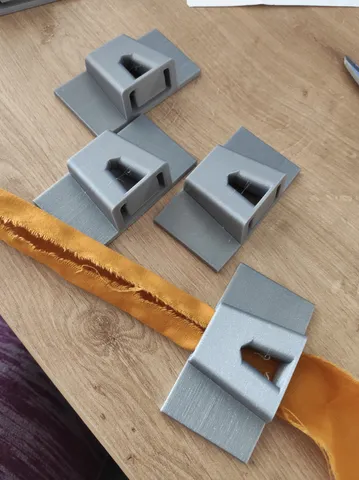
Then prepare the bigger printed piece for the assembly: Insert M3 square nut in the prepared slot and carefully remove the pillar with sharp knife (see the image bellow), otherwise the electronics can not be put inside the piece.
Finally assemble the piece together. Start with the potentiometer, then screw in the board (use the same screw as was in the original box). Finally cover the box with the second piece and screw in a bolt to hold the cover.
The dimmer corner piece. The marked pillar needs to be removed in order to fit the electronics inside.
Tags
Model origin
The author marked this model as their own original creation. Imported from Thingiverse.