BEDSIDE TABLE - NIGHTSTAND ( PRINT-TABLE #1)

Description
PDFOVERVIEW
This is the first prototype of a series of furniture pieces developed around a “construction kit” philosophy, in which printer-sized components can be simply assembled with minimal experience to create customised furniture pieces. All it takes to make a real piece of furniture, is some print time and a couple of hours of “Lego”-style fun!
I think this is the maximum volume that can be reliably created using this system and still result in a reasonably sturdy, usable piece of furniture but I'm sure others will prove me wrong in the future.
Over the coming weeks I will publish a couple of other designs incorporating variations on the “kit” parts, and subject to interest will then work on a range of parametric versions of each component so that they can be mixed and matched to create different custom furniture pieces.
You can find my END TABLE at this link , and my BOOKSHELVES here.
I use Ikea “Aptitlig” 48 x 28cm bamboo chopping boards for the timber parts. As they provide great value and a reliable renewable working surface. I have trimmed them of course to suit my own particular requirements, but if you don't have basic skills or tools, there's no reason why the top at least couldn't hang over the edges, and if you are prepared to accept a slightly less rigid result you could delete the cross brace and widen the structure to the width of the board. (In that case perhaps it would be smart to add a couple of the rigid brace parts to the front as well!)
A NOTE ON RIGIDITY AND STABILITY
This is the least rigid of the three designs I have published to date. Assembled with care, the structure is quite rigid, more than enough for day to day use, but it can and it WILL twist and wobble a little across the front if you wiggle it. If this is a concern it can be easily fixed by adding and additional pair of BRACES at the front (**braces to be uploaded approximately 27 April - as a retrofit option).
Alternatively using the top and bottom brace parts from the END TABLE in a combination of your choice will eliminate the twist, which is the result of having the shelves completely “floating”.
Please remember it's not a stool, and as with any furniture piece - using it beyond the limits of its designed intent may not end well!
BEFORE YOU START
May I recommend you print a test piece to check the fit and assembly processs? Two parts of a HUB_30, two parts of a CONNECTOR and possibly a BRACE_100 will be more than enough to get you hooked!
UPDATES
If you have a question, please ask and it will be addressed.
24 April - screw sizes defined
25 April - added crossbrace assembly photos
27 April - alternative front top brace added. (Description at bottom of page)
26 May - added note on Rigidity
DIMENSIONS
346 x 266 x 490mm high (13.5 x 10.5 x 19.25 inches)
MATERIALS REQUIRED.
1 kg of PLA filament of your choice printed with a 0.6mm nozzle and 15% infill.
2 x Ikea Aptitlig chopping boards - or the table top material of your choice.
10 x grams or so of Cyanoacrilate (Superglue) - I've used both expensive and generic brands and have had no problems with using the cheap “hobby” tubes in this application.
8 x Panhead Screws about 15mm to fix the Top and Shelf (It's obvious but make sure they are not so long that they go through the table top)
2 x Panhead Screws about 4mmx 25mm (6G x 1") long to fix the BRACE
4 x 25mm long M4 (5/32" will be fine) ( bolts and nuts for the CROSSBRACE fixing.
PRINT SETTINGS
I’ve printed with a 0.6 nozzle 3.0mm QUALITY mode in Prusa Slicer but if you only have a 0.4mm nozzle 3.0mm DRAFT mode worked well in my test pieces.
More infill might add to the rigidity of the structure - I've been happy with the 0.6mm nozzle wall thickness - with the standard number of top and bottom layers.
While the finished table is by no means a rigid box, it's more than sufficient for its intended purpose.
PRINTED PARTS
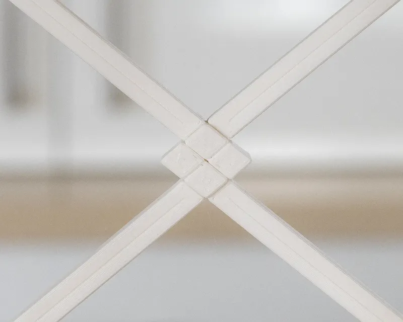
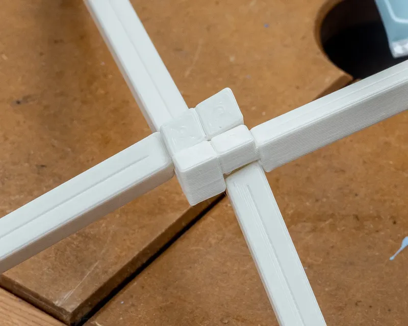
The HUBS, POSTS and Rails are made of two identical halves.
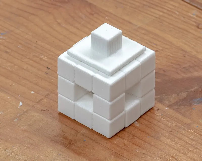
HUBS_30 - 8 required - print 16 parts
POST_280 - 4 required - print 8 parts (note these must be placed diagonally on the build plate so can only be printed one at a time)
RAIL_180 - 4 required - print 8 parts
LEGS_120 - 4 required
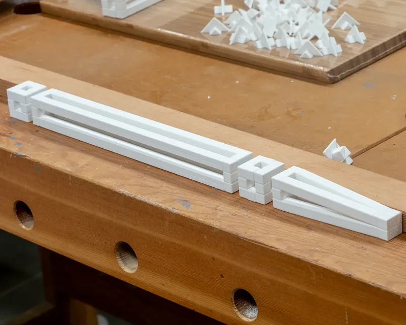
BRACE_100 - 2 required
CROSSBRACE - 1 required - print 2 parts
CROSSBRACE CLEATS - 4 required.
CONNECTORS - 20 required - print 40 parts (to join during assembly)
TOP MOUNTING CLIP - print 4
TOP CLIP SPACERS - print 4
BOTTOM SHELF MOUNTING CLIP - print 4
BOTTOM SHELF SPACERS - print 4
OPTIONAL -DECORATIVE FRONT BRACE - refer photo at bottom of page
ASSEMBLY
Now that you have your bench loaded up with a zillion parts, it's time to make a table!
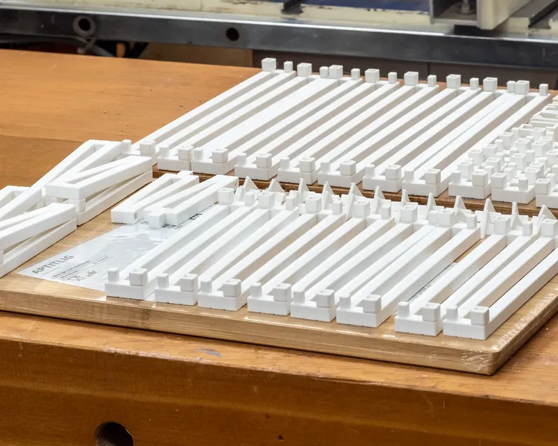
These parts are designed with minimal tolerances mostly 0mm, depending on your printer they will push firmly into place, or may require some very slight processing with a sharp blade to remove any elephant's foot (unlikely) or other little printing artefacts. An emery board or light sandpaper will help if you are really stuck.
My parts at worst need a gentle bump with the palm of my hand to fit - if you need more than that stop and work out what's wrong! (A tap with a tiny hammer probably won't hurt if you are SURE everything is in place!)
Use a small amount of CA glue (Super Glue) on each mating surface. I prefer not to use any accelerator to allow a little working time if necessary.
Hold or clamp the parts for a few minutes until the glue sets to ensure a nice tight connection, you don't need anything fancy here, but if you have spring clamps or rubber bands it will save a bit of “holding” time.
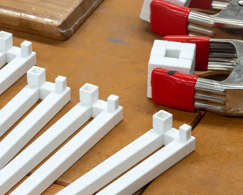
All of the hubs, posts and rails comprise two identical pieces - a drop of glue on each INNER face of the mounting sockets is all that's required.
Once you have all of the parts joined, lay them out on a bench so you can easily keep track of where you are in the process - make sure the LEG is lying on one of it's flat (not tapered) sides to make it easier to keep the connections in line.
I think it's better to glue the two pieces of the connector together at the same time as assembly - that will ensure no misalignment. Place a drop of glue on the connecting faces of one half and slip it into place then repeat for the second. Work quickly though as it's easy to glue the meeting faces in exactly the wrong spot if the glue goes off too quickly.
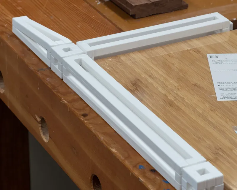
You don't need any special tools, but I use the square edges of the chopping boards to check for square as I go along.
When it's completed you'll have a nice shadow recess at each joint which makes the assembly process very forgiving. Don't sweat if you have small discrepancies, the lines of the finished piece are broken up to make them disappear as if by magic.
Remember it's a 3D printed furniture piece you are making, not a piece of jewellery - if you are worried about the quality of your print or assembly - don't be. It will look fine from a metre or two away.
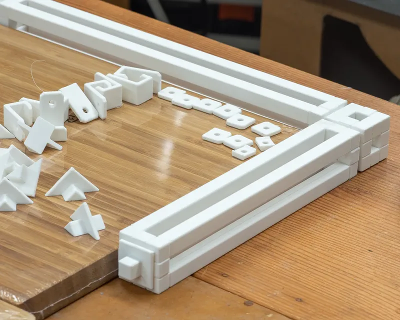
In the above photo you can see the top is nice and square ready to be joined.
It's obvious but make sure that when gluing the sides that the tapered bottoms are in opposite orientation. I've done this many times making furniture and almost always get confused at some point! Use a bit of masking tape to remind you as you go.
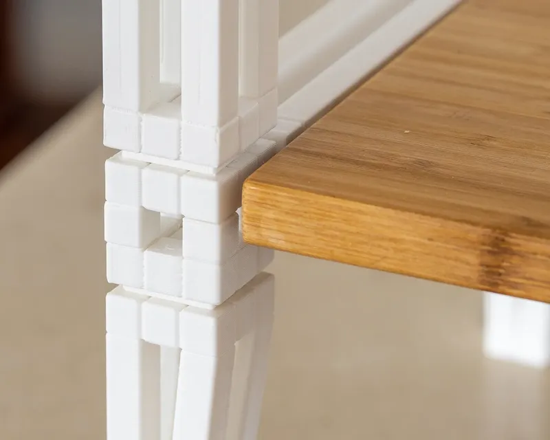
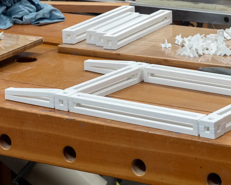
Once you have the side assembled as shown, glue in the BRACE_100 - this will ensure you don't make any orientation slip ups, and will make it a LOT easier to support the legs vertically when fitting the top.
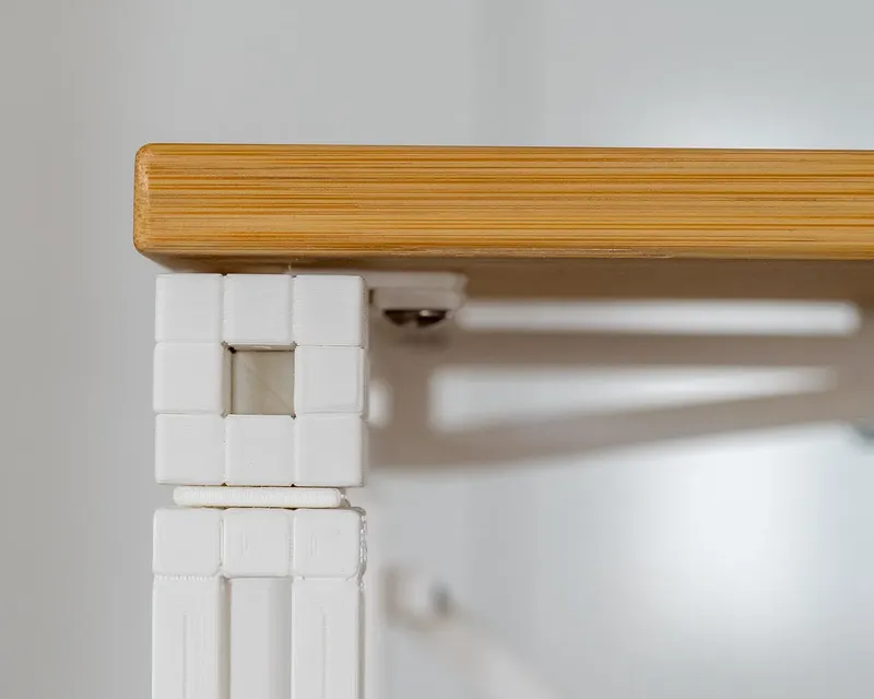
Cut the top to the finished size you require - in my example it's 352 x 272 mm which is enough to give a few millimetres of overhang, and at the same time cut off the tapered edges of the Ikea Chopping board. Fit a TOP MOUNTING CLIP to each inside corner of the top RAIL_180 The photo is showing the underside - so make sure the clip goes over the op of the rail. This will give a 3mm gap and a “floating” effect to the top. A drop of glue on the clip will make it easier for you, but the TOP CLIP SPACERS lock everything neatly into place for a bit of added insurance. The photograph below is of the shelf, but it should give you an idea of how the clip fits.
Fitting the shelf neatly will require an accurate cut, but it's not too hard to do that with basic hand tools, and even easier if you have a friend with machines!
My shelf it 280mm wide by 265 deep. The width is the important bit as it has to fit between the RAILS. The photo again is upside down to view the underside, it's easy to see how the clip mounts - again a dab of glue will make this easier. The BOTTOM SHELF SPACER is an angled part that ensures a consistent shadow line between the shelf and the RAIL, and not coincidentally brings the top of the shelf level with the rail. If those things are not important to you, you can delete it, but make sure your top fits well between the rails to assist with bracing.
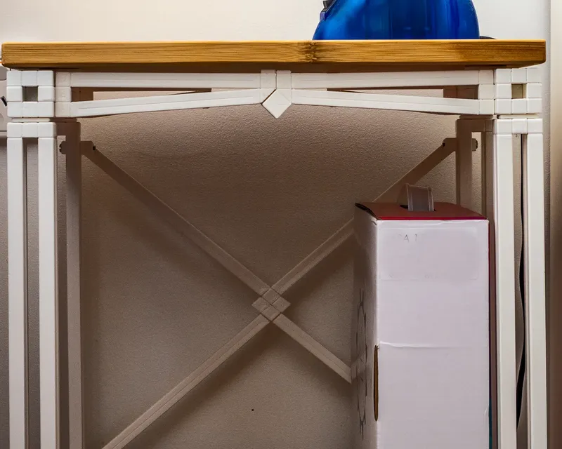
Speaking of bracing - if you have built the frame to the dimensions shown, grab the two bracing pieces you printed earlier and overlap them like a good old school wire puzzle.
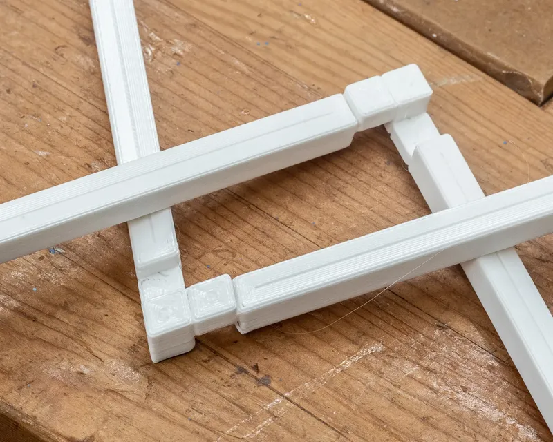
They have minimal clearance so a bit of a twist/click knack is required to connect them but it's very satisfying when they snap into place and stay there without any glue- just move them in to position as in the photo below, and carefully FORCE them into place!
You can skip the bracing if you wish, it all works fine without them but they add a lot to the stability of the finished table.
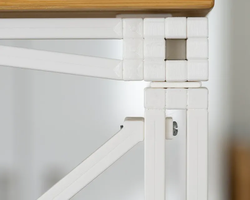
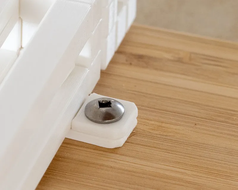
To fit them in place you'll need some 25 mm or so long bolts. Run the bolt through the CROSSBRACE CLEAT and insert it vertically between the post uprights. When it is in the ‘cavity’ you can turn it through 90° and using a screwdriver to apply pressure, hold it in place. Fit a nut into the CROSSBRACE recess, and tighten. It's a lot harder to describe than to do.
Don't glue the CLEAT in place as you will be able to apply a little tension on the CROSSBRACE if necessary, but sliding it along the track created by the post.
If you have got this far, I hope all has gone well and you have a piece of furniture of which you can be justly proud. I am certainly very happy with mine!
There is a lot of documentation here, and I'd really appreciate any feedback on anything that's not clear or in need of correction.
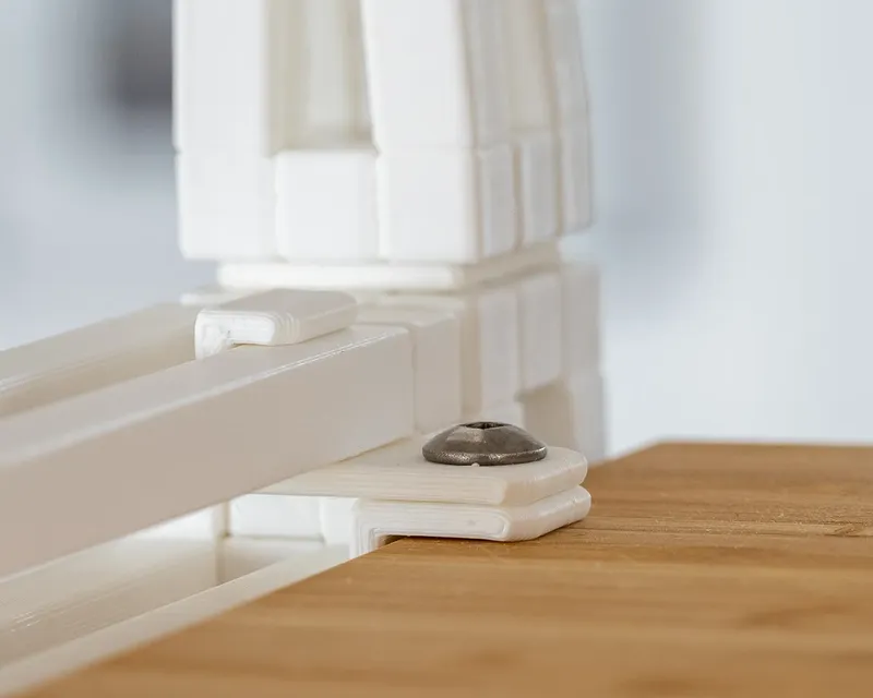
OPTIONAL DECORATIVE FRONT BRACE
I have designed an optional printed front brace - it's presently in one precise dimension only - but I will modify that on request. Note in the photograph it's not fitted but simply resting in place - hence the gap to the table top and at the connection point. It does fit well and I prefer this look, but my wife doesn't, hence the temporary fitting!
Tags
Model origin
The author marked this model as their own original creation.