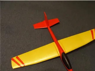
Eclipson model A removable HTP modification /Eclipson A modifikace pro odejímatelnou VOP
Description
PDFI liked Eclipson model A (free version), which I would like to use as micro glider. Therefore I made modifications on it like folding propeller and removable HTP.
For the removable HTP, I did not modified design of existing parts (Fus5 and HTP) and printed them as designed. All modification were made on printed parts, before they are glued together.
There are required three new printed parts and nylon screw M3x25 (cut to 3x23). The parts are:
- HTP connector, to keep both HTP parts (24 and 42 on schema) together, providing required space hole between them in front part and having hole for fixing screw.
- Nut for the M3 screw, inserted and glued into top part of Fus5 (part 9)
- Reinforcement for upper part of Fus5, used also as washer under M3 screw head.
All those three part must be printed from standard material (PLA/PETG…, not LW-PLA!)
Build instructions:
- At both centre parts of HTP cut small hole for connector (see pictures). The connector has to be placed just behind the HTP support. Grind off it, if required, the side parts must be lower than the central part. Due correct printing, bottom is printed as flat, the narrow bottom part (0,6mm) needs to be cut/grinded off.
- Using the connector, glue both parts of HTP together. Then remove additional material (see photo).
- The nut is designed to be printed without M3 thread. It was made after printing by standard M3 screw tap. If you haven’t any, it is also possible to use modified or heated M3 metal screw to create thread in it. Then check, if the nylon screw can be easy screw on. It is necessary operation before putting the nut into Fus5 part.
- The modification of Fus5 must be done between you glue Fus5 to rest of fuselage.
- Remove rear part of crossbar where HTP had to be originally glued. Leave only 27mm at front (see detail at one of photos). You can cut it or use soldering iron, as PLA or LW-PLA can be easy removed by heat tool.
- Use pin, narrow knife or soldering iron to make hole in top of Fus5 HTP slot. The center of hole should be 27 mm from the Fus5 end, respectively 102mm from Fus5 front end (where glued to Fus4) – for details, review the same photo as in previous step.
- Use straight artery forceps, or at least long tweezer to insert the nut into top part of Fus5 (part9). The small square holder is designed just for this usage. Push it toward the rear as possible. Control the position by hole, created In previous step. Make another hole in bootom part of Fus5 and glue there the reinforcement part.
- Try to place HTP and check the holes are in correct position. Use the M3 screw to check, the THP can be fixed here You can use Vaseline for the screw to prevent gluing it.
- Once the nut is on correct position, you can glue it (use drop of cyanoacrylate, or skewer / rod to get glue at nut.
- Glue also the bottom reinforcement part. Check the M3 screw not glued!
- You can use sanding paper to clean edges of the reinforcement part.
CZ
Pro variant s odnímatelnou VOP vytiskněte všechny díly z LW-PLA standardně. Modifikaci je třeba ale dělat před slepením.
Budete potřebovat nylonový šroub m3x25 (uříznutý na asi 23mm) a tři nově tištěné díly:
- Spojka VOP, spojující díly 24 a 42 do jednoho celku
- Tištěná matice pro M3 šroub
- Zesílení spodní části trupu (Fus5), sloužící též jako podložka nylonového šroubu.
Všechny tyto tři díly je třeba tisknout z pevného materiálu (PL/PETG… nikoli LW-PLA!)
Instrukce pro úpravu:
- Do centrů obou částí VOP je třeba proříznout/propilovat díru pro spojku (viz obrázky) Spojka je umístěna hned za nosníkem (přilepena k němu). Kvůli tisku je navržená s robnou spodní stranou, ale zeslabené části dole nutno odříznout /obrousit (asi 0,6mm, tloušťka LW-PLA dolní části VOP).
- Pomocí spojky slepte obě části VOP do jednoho celku, kontrolujte rovinu. Po slepení ořízněte/odbruste přesahující materiál.
- Matice je navržena bez závitu, je třeba ho vyříznout závitníkem. V nouzi lze použít pro udělání závitu I upravený nebo nahřátý M3 šroub. Nylonový šroub musí jít do matice dobře zašroubovat před jejím zalepením do zadní části trupu (Fus5).
- Je třeba odstranit zadní část příčky trupu. Ponechte pouze 27mm od náběžky. Lze uříznout nožem nebo odstranit pájkou, co odtaví filament.
- Pomocí ostrého nože nebo tlustého špendlíku udělejte dírku pro matici. Střed by měl být 27mm od konce trupu, respective 102mm od dělící roviny trupu Fus5. Je naznačeno na jedné z fotek.
- Použijte ideálně pean, nebo alespoň dlouhou pinzetu pro umístění matice do horní části konce trupu. Plošk ana matici slouží právě na uchopení. Pečlivě konrolujte pozici, zatím nelepte. Udělejte další dvě dírky v dolní části trupu, aby tam bylo možno vložit zesílení.
- Vyzkoušejte (stale zatím bez lepení montáž VOP. Teprve, když vše sedí, možno zalepit kyanoakrylátem. Šroub doporučuji namazat vazelínou, případně zpočátku jen nabodovat, pak vyndat šroub o VOP a dolepit pořádně. Matice postačí uchytit kapkami kyanoakrylátu zevnitř trupu (případě pomocí špejle).
- Okraje zesílení (podložky pod šroubem možno přebrousit.
Tags
Model origin
The author hasn't provided the model origin yet.

