Delta-P Extruder

Description
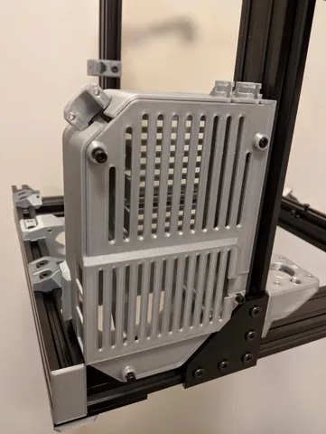
PDFThis is a customized MK3S extruder called the Delta-P.
Link to online 3D model viewer: https://a360.co/2BwxRKb
Update 04/04/2021
Fan duct completely redesigned:
- Easier to print
- Better cooling
- Refined flow path
- CFD optimized
- Even cooling front to back and left to right
- Improved visibility of nozzle
Many thanks to the prusa3D discord server for all their feedback and for doing the CFD analysis!
Files (stl and stp) for this updated fan duct included in their own folder below.
Update 04/12/2020
Updated custom firmware to v3.9.0
Update 2/27/2020
Updated fan duct to make bridges and overhangs easier to print
Strengthened 56 tooth pulley by adding internal perimeters
Update 12/18/2019
Updated BEAR varriant X carriage belt slots to make it easier to insert belts
Update 10/24/2019
Updated MMU2 instructions
Added option for custom IR sensor PCB for use on MMU2 version of extruder
Update 10/22/2019
Improved fit of Bontech idler in the MMU2 Idler Door for improved reliability.
Update 9-15-2019:
Fixed a couple problems on the BEAR x carriage
Update 9-9-2019:
Cleaned up and consolidated all the included files to make it less confusing
New part fan duct and fan mount
New option for BEAR or STOCK compatible X carriage
New one peice 56 tooth pulley
Update 9-7-2019:
Updated instructions for 3.8.0 firmware
Update 8-4-2019:
Added MMU2 version
Updated material recommendation for extruder body/cover and x carriage to ABS
Update 6-24-2019:
Strengthened PINDA mount to be less prone to sagging
Benefits:
Much less heat soak from motor to filament
Improved extruder linearity
Lower extruder mass (due to smaller motor)
strengthened PINDA mount less likely to sag
Improved visibility of nozzle
Looks cool
Acknowledgments:
The idea for this type of extruder mod came from user guy-k2, also known as BunnyScience from thingiverse:
https://forum.prusaprinters.org/forum/profile/94779/
https://www.thingiverse.com/BunnyScience/about
Many of these models were adapted/remixed from the optimized MK3 N4A-XT extruder .step files created by user butterworthdesign:
https://forum.prusaprinters.org/forum/profile/70771/
https://www.myminifactory.com/object/3d-print-butterworth-design-prusa-mk3-mk3s-r4-extruder-mod-filament-path-alignment-and-indirect-mk3-filament-sensor-86329
Print instructions
Recommended print settings:
PETG recommended for all parts
ABS or other high temp materials will also work
4 perimeters
0.40 nozzle
0.20 layers
0.10 layers for MMU2 idler door
20% or more infill
These parts require supports (don't use auto supports, position support enforcers manually):
-Motor Mount
-Extruder Body
-Pulley Mount
-Fan Duct
Included Files:
There are 3 base configurations of the Delta-P extruder, each with a STOCK or BEAR x-carriage option:
MK3-STOCK-complete.3mf
MK3S-STOCK-complete.3mf
MMU2-STOCK-complete.3mf
MK3-BEAR-complete.3mf
MK3S-BEAR-complete.3mf
MMU2-BEAR-complete.3mf
STEP files are also included for easy remixes:
MK3-STOCK-complete.step
MK3S-STOCK-complete.step
MMU2-STOCK-complete.step
MK3-BEAR-complete.step
MK3S-BEAR-complete.step
MMU2-BEAR-complete.step
Required hardware:
Various lengths 3mm screws
3mm Square nuts
3mm hex nuts
1x 3mm set screw
2x 3mm x 25mm steel shaft
1x 5mm x 45mm steel shaft
1x 16 tooth x 8mm timing pulley 5mm bore
140 tooth x 6mm closed loop 2GT timing belt
3 x 1050ZZ bearings
stepper motor, PN: 17HS10-0704S
1x MF63zz flanged bearing (MK3 only)
1x M3x6 set screw (MK3 only)
1x spring from a ballpoint pen (approx 4.18 OD, 3.4 ID, 16.25 long)(MMU2 only)
1x 3mm x 8mm steel shaft (MMU2 only)
1x 3mm locknut (MMU2 only)
1x 2mm screw (MMU2 only)
1x 4mm OD 2mm ID 13mm long PTFE tube (MMU2 only)
Filament sensor:
The IR sensor is installed just like a stock MK3S. Instructions for the laser sensor are available here:
https://www.myminifactory.com/object/3d-print-butterworth-design-prusa-mk3-mk3s-r4-extruder-mod-filament-path-alignment-and-indirect-mk3-filament-sensor-86329
Instructions for MMU2 IR sensor are below.
Pulley shaft:
You will need to grind flats into the shaft for the set screws in the pulley and Bontech gears.
If the shaft won't fit through the bearings you can chuck it in a drill and sand with 400 grit until it does.
Pulley spacer:
Orient the pulley so the hole for the square nut is facing the back of the extruder. The spacer goes on the back side of the pulley with the larger diameter against the pulley. See .step files.
Alignment pins:
There are two sets of holes for 3mm X 25mm alignment pins between the motor mount and pulley mount. These pins force the parts into alignment and ensure your pulley bearings are lined up straight.
They are a tight fit and you will need to use force to install them. Use a drift pin of some type if you need to remove them. Do not try and pry the parts apart with the pins in place or you will likely break something. (ask me how I know...)
X carriage:
Take care to not let the pulley shaft extend too far aft and interfere with the x carriage.
E-Steps:
Very important! Update printer EEPROM to account for drive ratio reduction by executing these commands in a terminal:
For 3.7.2+ Firmware:
M350 E16
M92 E490
M500
For earlier Firmware:
M92 E980
M500
Gcode explanation:
M350 Exx sets extruder uSteps
M92 Exxx sets extruder eSteps
M500 saves the settings permanently to EEPROM.
You can double check that the setting saved by sending M503
MMU2 IR Sensor Configuration:
PLEASE READ CAREFULLY
The sensor signal is inverted, therefore custom firmware OR a custom IR sensor is required.
Click here for custom firmware:
https://github.com/teookie/Prusa-Firmware/releases/tag/3.9.0
OR
Click here for custom IR sensor:
https://easyeda.com/teookie/inverted-ir-sensor
One or the other (custom firmware or custom sensor) is reqired; NOT BOTH. Pick the method that seems easiest to you. I am running the custom IR sensor currently, but I ran the custom firmware for several months previously.
If you choose to use the custom firmware , you will need to remove the 90 degree header from the stock IR sensor and either replace it with a straight header, or directly solder the wires onto the board.
MMU2 IR Sensor Calibration Procedure:
-Ensure bontech gears are clear of filament
-Back out the lever screw so that the flag is completely outside of the IR sensor gate
-Use the sensor status menu on LCD to verify IR sensor is reading "1"
-Slowly turn in the lever screw just until the sensor state changes to "0"
-Preheat hotend to 215° C
-Use octoprint or a terminal to rotate the extruder motor
-Verify that the sensor state remains at "0" for a full revolution of the bontech gears; if state fluctuates between 0 and 1, turn in the screw a small amount at a time until it is solidly "0" for a full revolution.
-Turn the lever screw in an additional 1/16 turn
-Calibration complete
MMU2 additional info
See the photos for a cross section showing how the lever, spring, and idler door go together.
Don't forget to put the PTFE in the top of the extruder under the cover.
Extra: Light Bar:
If you want a light bar that clears this extruder at max z height see below:
https://www.prusaprinters.org/prints/3244-z-tops-with-integrated-light-bar-supports
Model origin
The author remixed this model.