SainSmart CNC 3018 ProVER Parametric Spoilboard (and others) -- Source Included

Description
PDFThis is a CNC spoilboard I coded after looking at a few designs around the web. I wrote it for my SainSmart CNC 3018 ProVER with the Y extension (3040). If you have this machine, this may work for you, but check that the measurements are not out of bounds for your machine.
Examine the source code. Most values are variables that can be modified to suit your setup.
I used MDF from Home Depot, a big box hardware chain in the USA. I got the boards cut pretty close to size in the store, taped two together with blue painter's tape, clamped them down and let the machine do the work.
Creating the GCode
Importing Models into Fusion 360
To generate the tool path, I used Fusion 360. It took me a while but it worked out. I found the best way was to go to Design and Insert Mesh, then I converted it to a solid and did a 3D Pocket operation.
Autodesk has a guide for importing your .3mf or .stl file into Fusion 360.
They also have this guide:
This article from Sainsmart should help get you started to generate the .nc (gcode) file:
https://docs.sainsmart.com/article/j3nxnaoejh-fusion-360-quick-start-guide-for-3018-pro-prover-cnc-
Creating the GCode from Milling Operations
You will have to allow some time to get used to the interface -- there are many options. Check out some videos on the process on YouTube. Here are two:
https://youtu.be/g9RJZXiogSY
https://youtu.be/cmy9tZrC5Gg
Cutting the MDF Board
I used a 3.175 mm bit, and I think I did about 0.2 mm passes as I was afraid to go too deep with the cuts. This was my first CNC design.
I used CNCjs to cut the spoilboard.
Optional - Plastic Screws
I was, and still am, scared I will drive the cutting bit into a metal screw or bolt. I made the mounting bolts out of PETG. It is not perfect -- at this point the MDF slips a little bit if the board is pushed with a little force with 3 bolts attached. I may try hair spray on the bottom of the spoilboard. I may also try to use more bolts. :)
PETG Bolt Update: I had bad luck with them. I had all 7 bolts installed on my Y-extended bed with regular 3030 t-nuts and it still slid with a larger load / force. I switched to regular metal bolts and it went away.
I considered, but did not try, metal washers. That may work, but I don't think so, at least with PETG. When they get tight, the hex head strips. Perhaps a slotted head?
For those of you who can print with stronger filaments, if you find something that works, let me know – I haven't gone beyond PLA and PETG yet.
I never did try the hair spray, and there is always the good old blue tape and super glue mounting trick. I think the bolt method might be easier?
You decide.
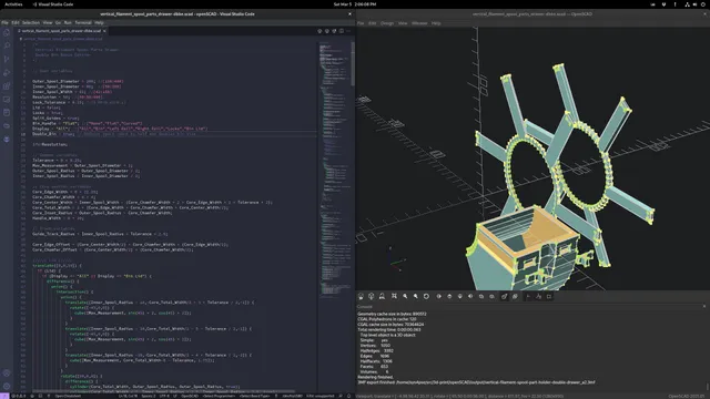
Modifying this Print in OpenSCAD
Some of you might be intimidated by OpenSCAD. If so, this is for you.
The .scad file is just a text file and I (think) the variable names are clear enough so you can make your own changes. It is a parametric model and should adjust itself accordingly.
Basically, you do these steps:
- Download OpenSCAD. It runs on many platforms and is free as in beer.
- Open the .scad file with OpenSCAD. You can also try the Visual Studio Code plugin -- that's what I normally use. You still need to install OpenSCAD to visualize your changes.
- Make changes.
- In OpenSCAD, hit the F6 key or Design -> Render. It wiil take a moment or two depending on your CPU, etc.
- Save as STL, 3MF, whatever.
- Slice and dice.
- Do a cartwheel (required).
July 22, 2022 Update Use the Customizer menu to change most of the variables. If that isn't enough, you can still change it manually.
Changelog:
- June 8, 2022
- Removed the curved edges on the sides of the spoilboard. At the time I thought they were needed but I can't see the point of them. It just makes for longer milling time when creating the spoilboard with the CNC. The calculations I made to create them had an incorrect offset and it made the other cutting calculations more complicated for no gain.
- Moved mounting holes to the sides of the board. The margin can be changed in the code, currently it is 15mm. See screenshot.
- Increased default countersink diameter to 12mm (for M6 screws). Countersunk screws are suggested or similar low-profile screws to avoid spindle collisions.
- Added option for clamp holes
- July 21, 2022
- One can use the Customizer menu in OpenSCAD to change the variables more easily.
- Added variable to change the clamp hole diameter.
Category: Tools
Tags
Model origin
The author marked this model as their own original creation. Imported from Thingiverse.