Runcam 2 integration for RC models - construction kit
Description
PDFThese are some files that help you fit a runcam 2 to RC models, primarily addressing CAD designers who make their own construction in a (vector based) CAD or (polygon based) 3D application.
Note that these files are not meant to build a fixture for the “naked” runcam but for the slide-in mount that is supplied with the camera - this is needed since the camera itself lacks a tripod thread.
Firstly, there is a file named “Runcam Mold Positive”, supplied as STL (for 3D) and STEP (for CAD). Use this as a “stamp” to “punch” a mold for the camera into a body using a boolean subtract command. Basic application is shown in the last picture in the above row.
Don't make the mold too deep - for the camera's front, the Lenses' field of view should not be blocked by the fuselage, and for the camera's back it's advisable to keep free access to the USB slot.
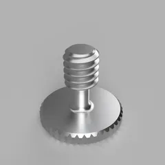
Secondly, I added a range of screws to fix the camera mount with. These are intended to be 3D printed. They have a regular ¼" UNC thread, but differ from normal (metal) tripod screws in shape and, of course, material to better fit the purpose of being used in a fuselage wall rather than on a tripod. They feature a pressure plain, can be screwed in and out without using tools, are lightweight, and in case of a crash landing you will surely prefer a broken screw over a broken camera…
With the screws, you can alternatively mount the camera to an existing model as long as the model offers a plane wall to drill a hole into. The 7 mm screw fits a minimal wall thickness of 3 mm, the 9.5 mm screw fits a maximum wall thickness of 6 mm. The screw hole should have a diameter of 8 mm.
Tags
Model origin
The author hasn't provided the model origin yet.


