Prusa MINI Nozzle Illuminator / LED light / led lamp

Description
PDFIntroduction:
This is a compact clip-on LED light for Prusa MINI/MINI+ to illuminate the nozzle while printing. It is designed to fit over the x-axis stepper motor, for easy installation. It solves the problem of the print head creating a shadow right at the nozzle, despite/because of lights mounted directly above the printer.
It is useful for checking bed adhesion on the first layer, or to get a good view of the nozzle while fine tuning print settings. Since it is mounted on the x-axis, it travels up and down with z-axis movements, which means its always at the same height as the nozzle.
There are two main versions: One for use with clear filament and one for solid color/opaque filaments. So even if you don't happen to have any clear filament on hand, I got you covered. All versions are available for three different LED strip widths: 10mm, 12mm and 14mm.
For power I'm using a 24V power supply with a 2.1mm barrel connector. This way the mod is completely reversible without any tools, you just unclip the light from the stepper motor, remove the power supply and your printer is back to stock.
I chose 24V LED strips because in the future, I may route the wires into the electronics enclosure, add an additional fuse and power switch and tap into the 24V supply of the MINI. Note: this kind of modification is more involved and will most likely void your warranty, so if you want to do this, you are doing so at your own risk.
Materials:
- printed parts
- 10cm piece of 1.75mm 3D printing filament
- 24V white LED strip of about 10cm length, 10/12/14mm width
- insulated copper wire
- 24V DC power supply
- heat shrink tubing
- DC barrel power jack of same size as your power supply
- solder
Print Instructions:
- PETG filament recommended, as the parts need to flex during installation on the printer
- for clear filaments use files from folder named clear_filament_xxxx
- for opaque filaments use files from folder opaque_filament_xxxx
- file names containing measurements in mm refer to the led strip width recommended for the part
Recommended Print Settings:
Layer Height: 0.2mm
Infill: 25% Honeycomb or Gyroid
Perimeters: minimum 2
External perimeters first option is recommended, as this tends to make the Dimensions more accurate, at least in my case.
Supports: None
If you use the included stl-files make sure to orient the parts with the flat surface towards the print bed. The included .3mf files already have the parts oriented correctly.
The supplied g-codes should print fine on most MINIs, however it is advisable to use the included .3mf files and load your favorite filament settings, to ensure the best print quality.
Assembly Instructions:
Prepare LED strip:
It is possible to buy LED strips pre wired with connectors, dimmers/controllers and compatible power supplies. If you are not used to tinker with electronics, this is the way I recommend.
For everyone else:
- solder wires to led strip (if your LED strip comes with wires attached, you can skip this step)
- cut wires to desired length (depending on where you want to mount the power supply)
- optional: solder power switch inline with the positive wire of the LED strip and insulate them with heat shrink tubing
- solder DC barrel power jack onto the wires of the LED strip and insulate them with heat shrink tubing Note: some power supplies come with connectors wired center-positive, some center-negative. This is usually noted on the power supply case. Connect your power jack accordingly.
Test LED strip:
Make sure you are not looking at the LEDs directly and have them facing away from your face. Some LED strips can be very bright! Connect the power supply (and optionally brightness controller) and test if everything works. Make sure to leave them on for a couple minutes and check if there is excessive heat buildup at the LEDs.
Note:
Some manufacturers of LED strips run them very close to their rated maximum, which makes them run rather hot. I noticed that my LEDs were getting quite warm, and after a couple minutes were almost too hot to touch. I compensated for this by replacing the surface mount resistors on the LED strip with ones roughly three times their value. This made the LED strips run much cooler and only reduced the perceived brightness by a bit.
Since not everyone is comfortable soldering surface mount components, here's what you can do if you have a similar issue:
- try a different brand of LED strip
- use a brightness controller/dimmer for LED strips
Mount LED strip:
Disconnect power from the LED strip by unplugging it from the power supply. Shorten the LED strip connected to your wires to about 10cm. Make sure you only cut the LED strip at the cut markers.
Place the LED strip inside the channel of the printed part as shown below:

If the wires are thick enough, they are held in place by friction. If that's not the case secure them with a drop of glue.
Mount Back Plate:
The printed parts have small octagon shaped holes in them. This way the holes should print closer to the desired dimensions, as polygon holes tend to print more accurately then circles.
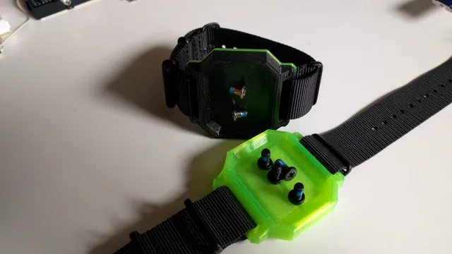
The back plate is secured with little pieces of 3D printing filament, acting as rivets:
Cut the end off of the filament at an angle. Place the back plate on top of the main housing to cover the LED strip. Then align the holes and insert the filament in one of the holes. Make sure it is all the way through the plate and protrudes into the hole of the bottom piece by about 2mm. Then cut the filament about 2-3mm above the plate as shown below:

Now press the filament in until it sits flush with the plate. You can use pliers, clamps or just flip it upside down and press it against a hard surface.
The result should look something like this:


It is not required to use all the holes, I just added some extras in case some come out too undersized. Also it is possible to slightly widen the holes using a toothpick or a drill bit/reamer. If the holes are slightly too big, the filament pieces can be secured with superglue.
Installation on the printer:
Installation is pretty simple: Just hold the light assembly in front of the x-axis stepper motor and slide it on. The front and back plates of the stepper are wider than the middle, so it may be required to flex the light assembly slightly to get it on. After that it should clip onto the stepper motor plate closest to the z-axis lead screw.
Note: It is recommended to install it on the printer while it is cold, to eliminate the risk of getting burned by the hot end. It is also a good idea to move the print head to the left to have more room for installing the light on the stepper.
As shown below the light only touches the stepper in 3 locations. There are two big gaps between the light and the stepper motor to insure good ventilation and cooling of both the light itself and the stepper. The part is also designed to have enough clearance to the heat-break, while the print head is in home position.


Cable management:
Now it's time to make sure the power cable of the lights don't get in the way of the printer. Since the cable exits the light close to the x-axis stepper cable, they can be routed together to the frame of the printer. They can be tied together with velcro cable ties, as this insures that there is no excessive force applied to the cables compared to zipties. It is important to make sure the cable does not get pinched or torn when the printer moves.
Final Result:
A well lit print bed/nozzle. Enjoy!

This is the second version for use with opaque filament:
It has a guard for the top LEDs to reduce the chance of being blinded when looking at it from above.


This is what it looks like in complete darkness:

In this shot the print bed only looks quite dark, because I focused the camera on the very bright LEDs:

The pictures don't quite do it justice, it looks much better in person.
Tags
Model origin
The author marked this model as their own original creation.