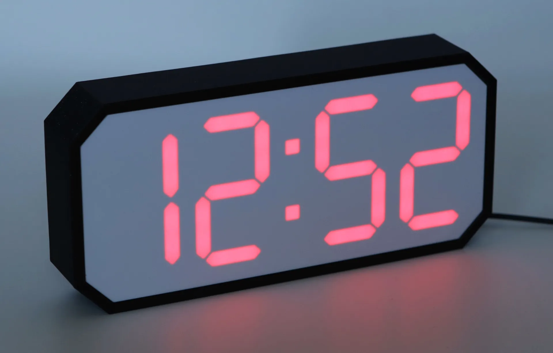
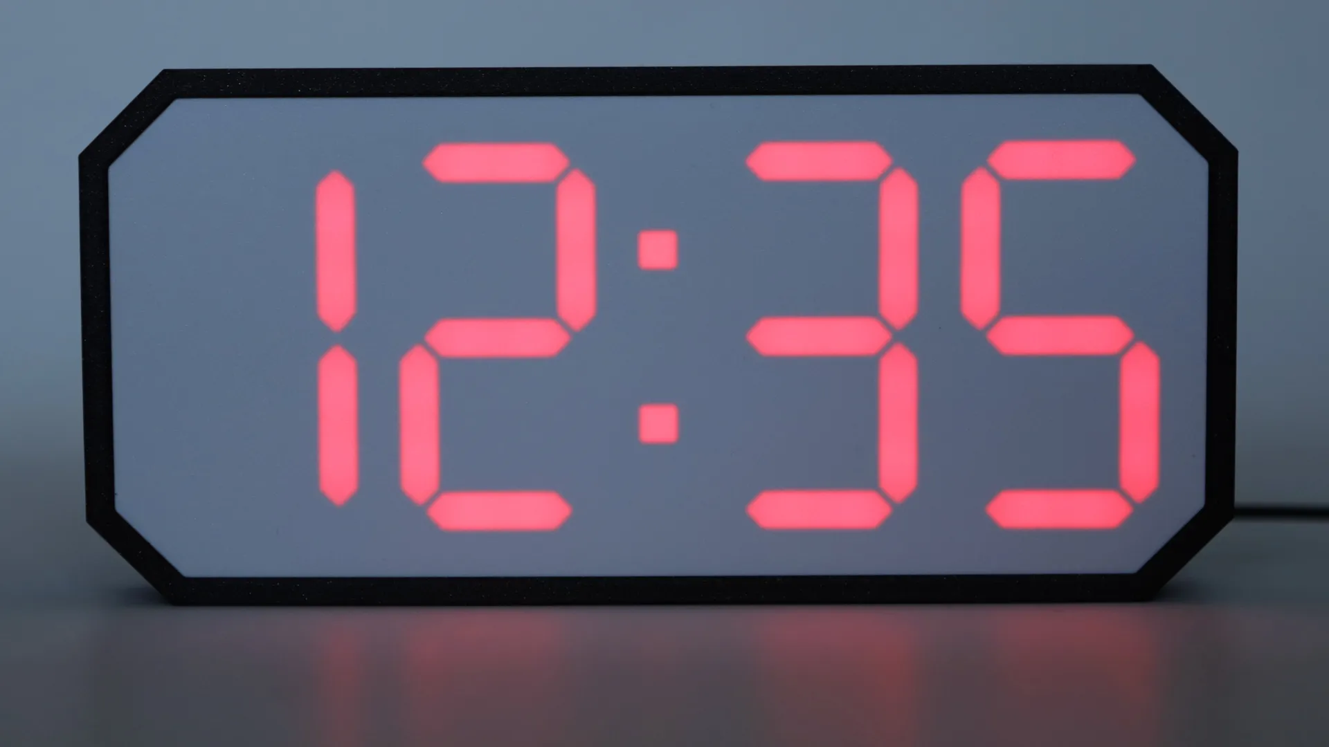
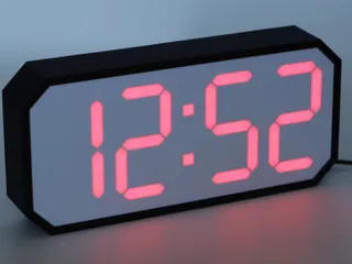
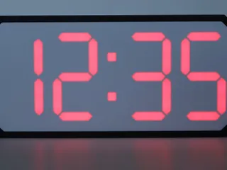
7 Segment LED Clock


Description
PDFIntroduction
My entry for the PrusaPrinters “Timekeepers” contest (Don't forget to give it a like...)
Some ideas for upcoming versions:
- Software
- DONE - Integrate WiFiManager for easier setup
- DONE - Configure the timezone/time offset in a Web GUI (set automatically during WiFiManager configuration)
- DONE - Show temperature
- OTA (Over The Air) Updates
- Set the brightness depending on time of day or a brightness sensor
- Buttons to change the brightness and color
- Hardware
- Back lid to mount it on a wall
- Bring down the thickness to around 30mm for wall mounting (40mm is fine for the desktop version)
- Buttons
Support my work
For non-Prusa parts and filaments, check out 3DJake (International, UK, Germany, France).
I'll get a small cut of any order you fulfil using these links (at no additional cost for you 😉).
If you want to support my work directly, you can buy me a coffee.
If you want to order a Prusa printer and earn some Prusameters (I will also get some), you can use my referral code "@Whity" at checkout or click one of the following links
(the code only works for the first order of each printer model):
| CORE One | CORE One Kit | MK4 | MK4 Kit | MINI+ | MINI+ Kit | XL | SL1S | SL1S+CW1S |
Also check out my other models.
Updates
30.05.2021:
- Added back lid without ESP32 mount (STL and Step file for customisation)
- Fixed a small issue in the code: The first digit of the hour doesn't disappear when switching from 23:59 to 0:00
02.06.2021:
- Updated frame and back lid files (Increased the cable opening from 3.5 to 4.1 mm to support thicker USB cables)
18.06.2021:
- The code is available at GitHub now (removed the .ino file from downloads)
- Made a lot of code changes:
- Implemented WiFiManager
- Splitted the code into multiple files and separated the configuration
- It's now possible to show the temperature of a given location in a predefined Interval
- Shows the status of the clock during startup
- It's able to display different characters now if needed (for upcoming features i don't know yet)
- Can show error codes “Er00” to “Er99” in case something fails (Very basic for now and not documented yet)
- Various small cleanups and improvements
Print instructions
The printer needs to be able to print at lease 240mm and therefore will not fit onto the MINI, I'm sorry.
The 3mf files are prepared to print right out of the box.
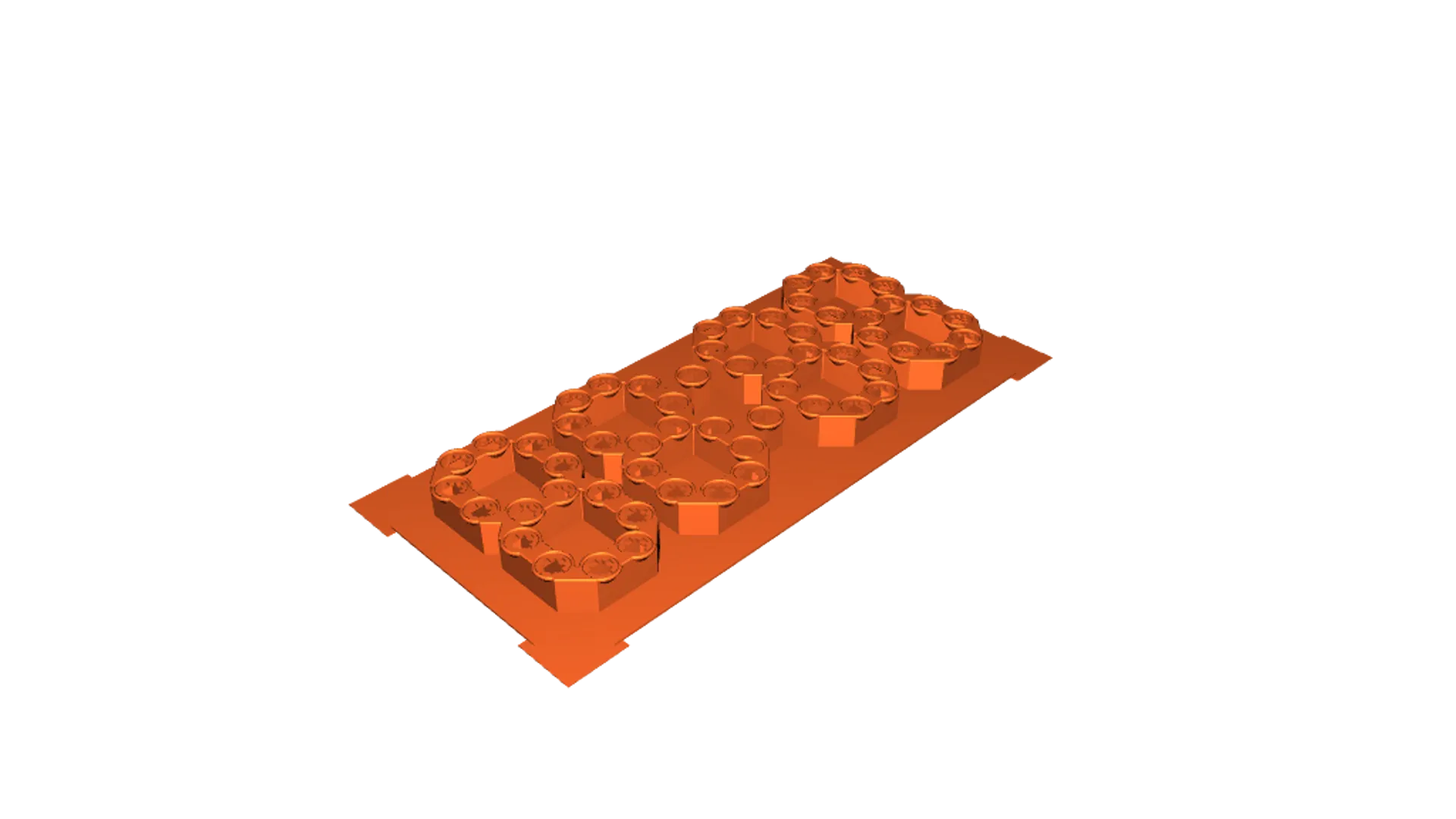
The “Segments” part needs a color change at 1mm (after printing the 0.8mm/4th layer). The first four layers should be printed in white, the rest of the layers in silver (ideally something that reflects, but doesn't let much light through). If printed completely in white, it will not look good at all. Don't try it, I did as a test, doesn't work at all.

Additional parts required
- ESP32 DEVKITV1 (ESP-WROOM-32)
Only this one will fit into the prepared holder on the back lid - W2812B LEDs (pre-soldered onto a round 10mm PCB)
- Logic Level Converter to convert the 3.3V signal to 5V
- Micro USB Power Supply
- Optional: A capacitor of around 450µF (I think it's not really needed, but doesn't hurt…)
Load the code
Download the most current version of the code from GitHub and follow the instructions there.
Assembly
Glueing in the LEDs
I used a hot glue gun to glue in the LEDs. Just worked very well for me in many projects and has the advantage, that you can get the LED out again much more easily in case you have to replace one.
This is the order in which the LEDs have to be glued in to work with the provided code (the two LEDs of the colon have to be the last ones):

Soldering the LEDs
I use blank wire for each segment and stranded/isolated wire to connect them. It's much easier and faster to use blank wire (you anyway should solder fast if you used hot glue…).
Do one path at a time and only solder it to one pad (I apply a bit of solder to one of the pads of each LED first and then just heating it up again to solder on the wire):

Then solder the second pad of each LED.
Repeat this for the other two paths:

The middle one is special, because it's the data line and the IN and OUT pads must not be connected. Use a side cutter to cut out a piece (or solder them one by one if you really like to):

And the third one:

At the end it should look like this:

Then connect the single segments with stranded/isolated wire:

Solder on a long enough piece of wire to connect the first data input:

The rest of the electronics

Just solder on long enough wires to reach the logic level converter or the LEDs with some extra wire (the two wires with larger diameter). The capacitor is optional. I added it because i had some flickering. Probably not needed.
These pins are needed:
- VIN (5V) & GND (Top right. The thiner ones will go to the logic level converter, the others to the LEDs)
- 3.3V & GND (Top left. To the level converter)
- D4 (below the left GND. To the level converter too)
Putting it all together
Slide in the segments into the frame from the side:


Push it down and make sure it snaps in properly:


On the back lid, cut off the bridge:


Glue in the logic level converter (There are different types of logic level converters. If yours is a different one, check out the data sheet how to wire them later):

Slide in the ESP32 (Install it as show, as it has two LEDs on the top side which will very likely shine through the front. You may can also desolder at least the red one, didn't try if it affects the functionality):


Solder on the wires coming from the ESP32.
In case of the logic level converter i used, the 3.3V & GND on the top, the 5V & GND on the bottom and D4 on one of the low voltage inputs (top right in this case).
Ignore the wire on the bottom right for now (I took the photo after wiring everything).

Put the prepared frame and back lid side by side and solder on the rest of the wires.
The 5V & GND should be soldered somewhere in the middle:


Plug in the micro USB power adapter and put on the lid:

And we're done:

Tags
Model origin
The author marked this model as their own original creation.