rotating miniature screw PCB clamp/vice 54 mm
Description
PDFPurpose
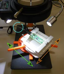
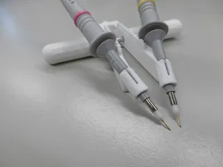
This very flat clamp can be used for inspecting, measuring and soldering under a microscope. For example miniature PCBs like ESP32 modules. or other small microcontroller boards. Features PCB edge slots of 1.6 and 0.8 mm, flat, right-angle and 45 degrees.
- It allows to increase the friction needed for handllng very small en lightweight boards
- It allows large fingers to not have to touch the board. More precise manipulation is possible using the LCD microscope display. When you make it part of your eye-hand motion visual feedback loop, it improves handling resolution immensly, saving time and help improving the quality of work.
- The rotating base can be positioned so that lighting of weakly laser-engraved IC top markings can be quickly checked under different incident angles.
- The stick can be used for positioning, clamping and tensioning. Note that there is (currently) no way to mechanically clamp/prevent the rotor to rorate relative to the base.
Design
The clamp features a 4mm thick rotor plate and a 7 to 54 mm adjustable beak width. Beaks are 11 mm high and 60 mm wide. The rotor can be held down by a 3mm square conical plate. This square base can be bolted down to a metal plate with four 90 mm spaced short M3 bolts, or magnetically using up to four 12mm x 5 mm x 3 mm magnets. 13x7x5 mm magnets can be glued into the recessions in the base.
Printing
For printing, I used a MK3 with standard silver PLA prusament and 0.10mm detail prusa 2.3.0 slicer settings, with “support on build-plate only” and 100% infill to prevent warping of the thin parts. Experimental sub-millimeter margins for play/smooth movement are already accounted for in the OpenScad model.
The stick needs to be printed right-up to get a good smooth round bearing. The sliding clamp needs to printed upside-down to get same alignment and visual quality as the other clamp, fixed to the rotor. The base and rotor need to be printed separately. The square base and clamps have a 2 or 1 mm round chamfer for looks and comfort, the dovetails and conical rotor do not feature chamfer.
Assembly
An M3 hex nut must be dropped in the slot of the stick. The slider needs a long M3 bolt preferably hex head M3x50 (galvanized) DIN84. Since M3 bolts over 40mm long can be harder to acquire, one can alternatively use a M3 thread-rod with a metal-glued M3 nut instead.
Tags
Model origin
The author hasn't provided the model origin yet.


